
30 : 1
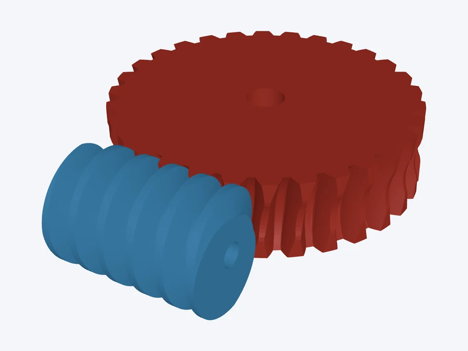

30 : 1 · module 2, one start
m 2 · 20° · ZA
The starter drive: a single-start module 2 worm turning a 30-tooth throated wheel, 30 : 1.
Set the module or pitch, the starts and the wheel's teeth, and get a worm and worm wheel that mesh: a high ratio in one step, with shafts crossed at 90°. Add bores, hubs and set screws, check the efficiency and self-locking, and download STL or STEP.
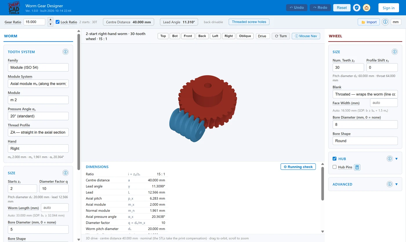
ISO 54 modules, axial or normal module system, or Boston Gear's 3 to 64 DP; 20°, 14½°, 25° and 30° pressure angles.
ZA, straight in the axial section; ZN, straight in the normal section; ZI, the involute helicoid; and ZK, shaped by a disc cutter of the size you set.
Ratios up to 400 : 1 in one step; the lead angle and the ratio show as you type.
The wheel is generated by the worm acting as a hob, slice by slice, so its teeth are what that worm would cut: throat, undercut and all.
A throated wheel wraps the worm for more contact; a plain cylinder is simpler to print or turn. Profile shift and backlash are settings.
The Running check takes a load, a speed and the friction, and gives the efficiency both ways, self-locking, sliding speed and the torques.
Round, D-flat, keyway, ISO 14 and ISO 4156 spline and hex bar bores with retaining rings; hubs with set screws or hub pins, on the worm and the wheel.
Proportions from SDP/SI and KHK. A worm too short or a wheel too wide gets a warning with one-click Auto-fix.
STL with print compensation, each part in its print orientation; one STEP holds the worm and wheel in mesh, with the sample shafts.
| Setting | Choices | Source |
|---|---|---|
| Size | ISO 54 modules (axial or normal); 3 – 64 DP | SDP/SI §9, Boston Gear |
| Thread profile | ZA, ZN, ZI, ZK | SDP/SI §9.2; Litvin |
| Pressure angle | 20°, 14½°, 25°, 30° | SDP/SI, KHK |
| Starts and teeth | 1 – 8 starts; 6 – 400 wheel teeth |
Printed and industrial, metric and inch, self-locking or fast. Each opens with the worm and wheel in mesh, ready to change.
m 2 · 20° · ZA
The starter drive: a single-start module 2 worm turning a 30-tooth throated wheel, 30 : 1.
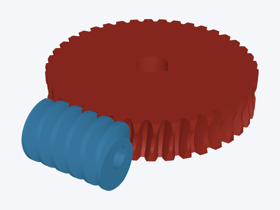

m 3 · 20° · ZA
A module 3 single-start drive on keyed 12 mm and 20 mm shafts, the wheel throated to wrap the worm.
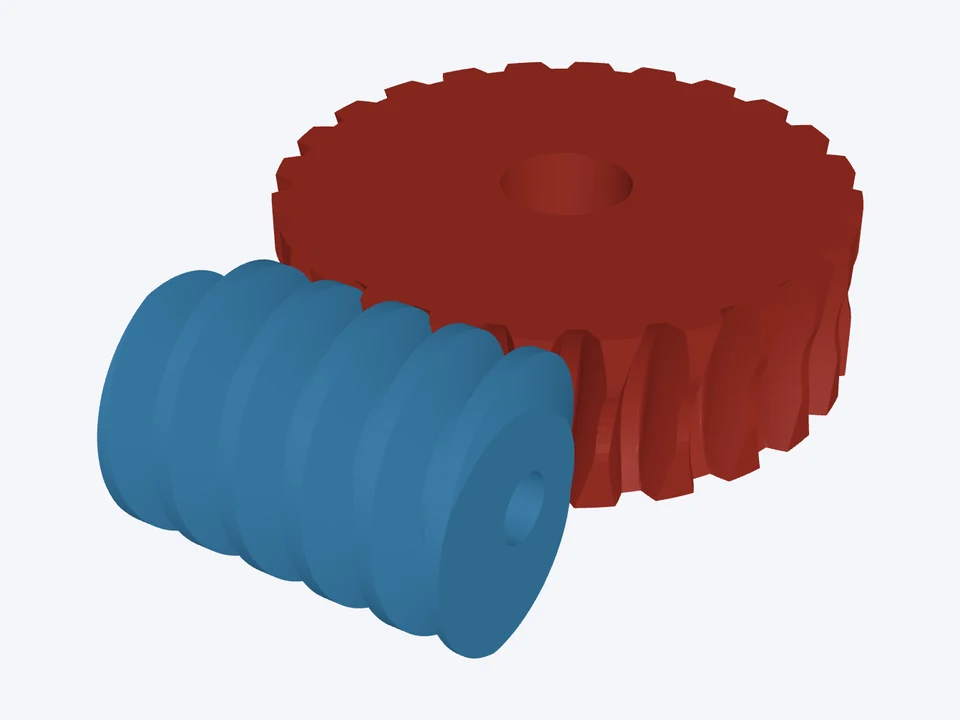

12 DP · 20° · ZA
A 12 DP single-start worm on a ¼" shaft driving a 24-tooth wheel on ½", Boston Gear style.


m 2 · 20° · ZA
A four-start worm for a fast, efficient 6 : 1 drive that turns either way.
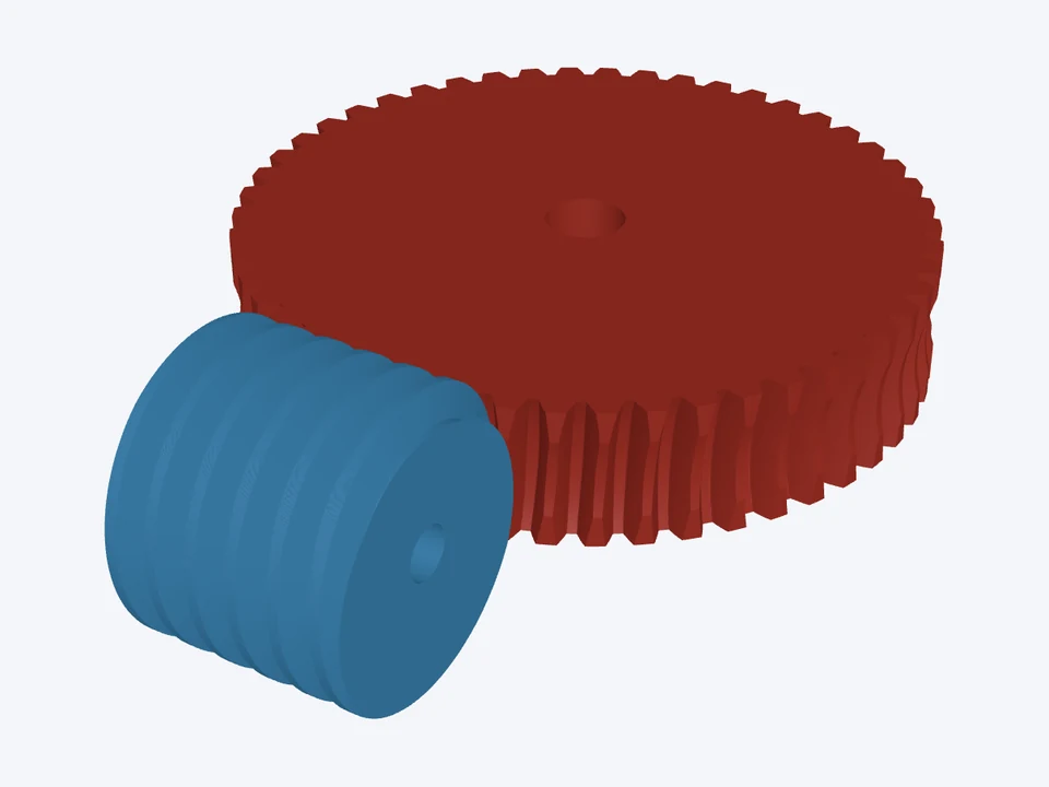

m 2 · 20° · ZA
A slim single-start worm (q 20) whose small lead angle holds the load when the motor stops.
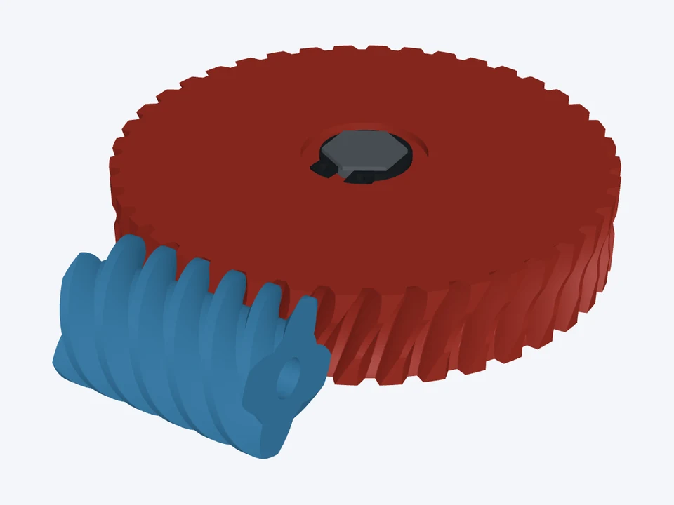

16 DP · 20° · ZA
A four-start 16 DP worm and a wheel on a 10 mm hex bar, held by a DIN 471 retaining ring.
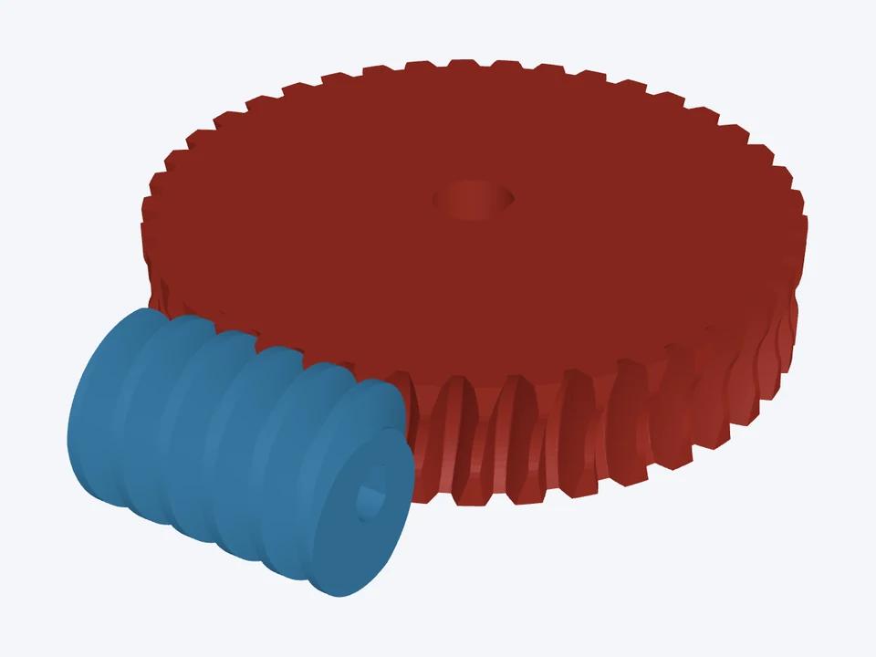

m 1.5 · 20° · ZA
A printable 40 : 1 reduction on 5 mm and 8 mm D-flat shafts, with 0.1 mm print compensation on both parts.
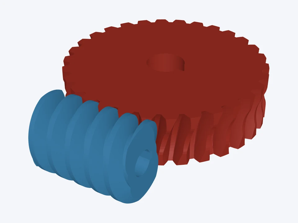

m_n 4 · 20° · ZI
A two-start involute worm sized in the normal system (m_n 4), on keyed 16 mm and 25 mm shafts.
STL (with your print compensation, for 3D printing) for the worm, the wheel and any sample shafts, and STEP at true size: one file with the worm and wheel in mesh. 2D drawings (DXF and SVG) are on the way.
Open the Running check: from the lead angle and the friction coefficient it works out the efficiency in both directions and says whether the drive locks in theory, with Boston Gear's and KHK's rules of thumb. Vibration can still back-drive a drive that locks in theory, so add a brake where it matters.
Yes. The worm prints standing on its axis and the wheel flat, and the print compensation goes into the STL only. A printed wheel is still plastic: keep the sliding speed low, and the app warns when it passes KHK's 1 m/s for an unlubricated plastic wheel.
Not yet. The app checks the geometry and works out the efficiency, self-locking and torques; a strength and wear rating will follow.
Yes. Designing and checking are free; downloads cost a few tokens, the same as the other tools, and one purchase covers every file of that design for 24 hours. See Pricing.