
20 : 30 · 1 : 1.5


XL 20T & 30T, ¼" & ⅜" Bores, Inch Set Screws
Imperial down to the hardware: an XL belt, ¼" and ⅜" shafts, and #8-32 and #10-24 set screws in captured nuts.
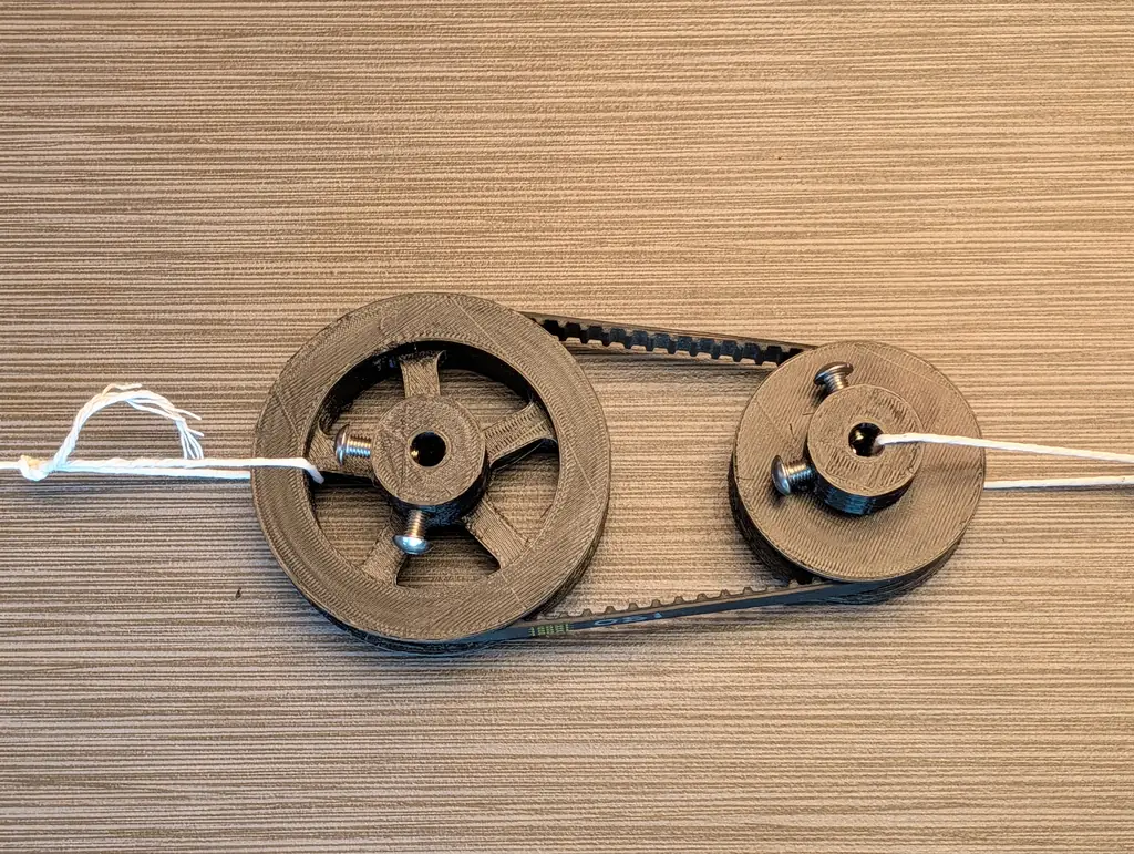
Printed and run on a 150XL belt: two M5 set screws per hub thread straight into hex-shaped holes in the plastic, with no nut or insert, on 8 mm bores; the 45-tooth pulley has five spokes and both print their flanges in place.
Using the CheapCAD Tools connector, design a two-pulley timing belt drive: XL belt, 12.5 mm wide, about 94.47 mm between centres, with 2 mm of extra face width beyond the belt. Pulley 1: 30 teeth, 8 mm bore, 0.2 mm print compensation, a hub 25 mm across and 15 mm tall with two M5 set screws threaded straight into hex-shaped holes in the plastic. Pulley 2: 45 teeth, 8 mm bore, a hub 25 mm across and 15 mm tall with two M5 set screws threaded into the plastic, and 5 spokes 8 mm wide on a 6 mm web round a 25 mm spoke hub, a 6 mm rim under the teeth and 3 mm fillets at the rim and the hub. Both pulleys: printed flanges 3 mm thick reaching 4 mm past the teeth, the top flange printed in place on breakaway print supports at most 5 mm apart. Check the design, apply any Auto-fix it suggests, then export both pulleys as STL and give me the download link.
Paste it into Claude, ChatGPT or any AI app with the CheapCAD Tools connector, and it designs this drive with you, checks it and hands you the files. How to connect your AI.
Imperial-XL-30T.stl — pulley 1, 30 teeth, without supportsImperial-XL-45T-P2.stl — pulley 2, 45 teeth, without supportsImperial-XL-30T-w-supports.stl — pulley 1 with breakaway supports under its top flange: print this oneImperial-XL-45T-P2-w-supports.stl — pulley 2 with breakaway supports under its top flange: print this oneFree STLs are CC BY 4.0, exactly the design that was printed for the photos, with its print compensation (pulley 1 0.2 mm). Open the design to change anything, tune the fit for your printer, or download STEP, DXF, SVG and the belt.
| Pulley 1 | Pulley 2 | |
|---|---|---|
| Pitch diameter | 48.51 mm | 72.77 mm |
| Outside diameter | 48.00 mm | 72.26 mm |
| Outside diameter, as built | 47.60 mm | 72.26 mm |
| Root diameter | 44.70 mm | 68.96 mm |
| Groove depth | 1.65 mm | 1.65 mm |
| Pitch line differential | 0.25 mm | 0.25 mm |
| Belt width | 12.50 mm | 12.50 mm |
| Face width (belt + clearance) | 14.50 mm | 14.50 mm |
| Minimum face width | 13.50 mm | 13.50 mm |
| Flange outside diameter | 55.60 mm | 80.26 mm |
| Flange past the OD | 4.00 mm | 4.00 mm |
| Minimum flange height | 1.00 mm | 1.00 mm |
| Flange inward of the groove | — | 6.00 mm |
| Minimum flange overlap | — | 3.00 mm≈ |
| Belt | 75 teeth · 381.00 mm | |
| Centre distance | 94.47 mm | |
| Drive ratio | 30 : 45 · 1 : 1.5 | |
Read from the generator's Dimensions panel for this design, which opens with no warnings.
Imperial down to the hardware: an XL belt, ¼" and ⅜" shafts, and #8-32 and #10-24 set screws in captured nuts.


The ⅜" L pitch for heavier inch-sized machines: ½" and ¾" bores with ⅛" and 3/16" keyways, and a 1/4-20 set screw on the larger hub.


Small and fine-pitched: 0.08" MXL teeth on 3 mm and 4 mm shafts, held by M2 set screws in hex-shaped tapped holes.


Printed and run on an S5M 690 belt: a 1 : 5 reduction to a 100-tooth wheel on eight spokes, whose top flange prints as a separate ring and glues on over 40 nubs, while the 20-tooth pulley prints its flanges in place.